
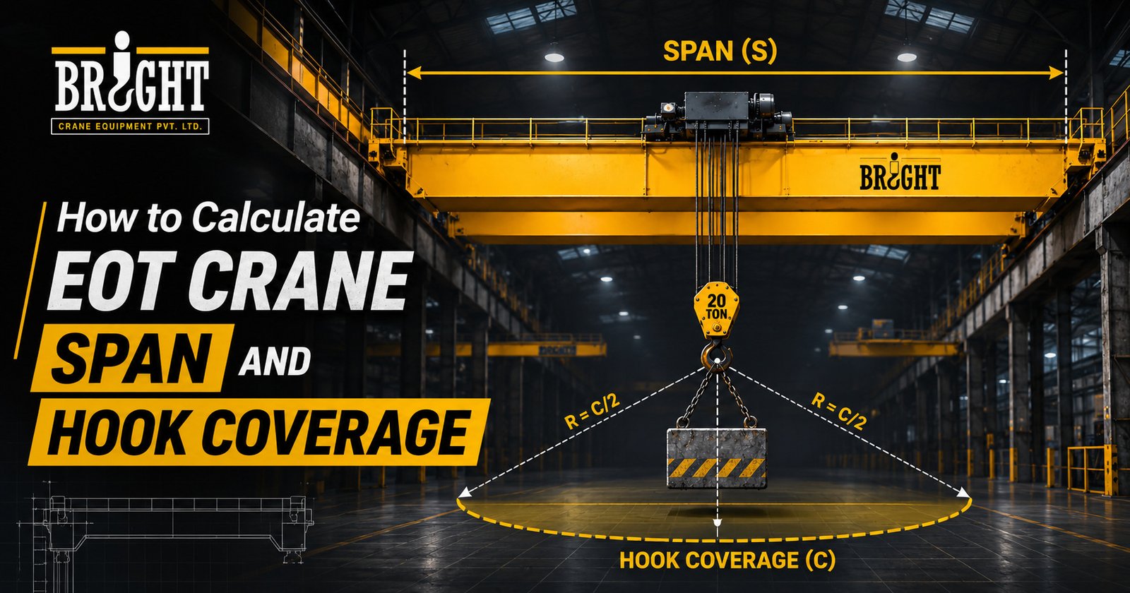
EOT crane span is the horizontal distance between the centrelines of the two runway rails. A common way to calculate it is: Span = building column centre-to-centre width − 2 × (distance from column centreline to rail centreline). Hook coverage is the area the hook can actually reach: Coverage width = Span − (left hook approach + right hook approach), and coverage length = runway length − (end approach at each end). Multiply the two to get the hook coverage area.
Choosing an EOT crane starts with two simple-sounding questions: how wide should the crane be, and how much of the floor can the hook actually reach?
Get the EOT crane span calculation wrong and problems follow quickly. The crane may not fit between the building columns, it may clash with walls or roof trusses, or its hook may leave large strips of floor that can't be served. Fixing those mistakes after the building is complete is expensive and sometimes impossible.
EOT crane hook coverage matters just as much. A crane with a 20 m span doesn't give you 20 m of usable hook travel. The hook always stops short of the runway rails and the runway ends, and that lost area needs to be planned for when you lay out machines, storage and loading bays.
This guide explains how to calculate EOT crane span, hook approach and hook coverage, with formulas, a worked example and the key EOT crane dimensions and design checks engineers use.
It's written by the engineering team at Bright Crane Equipment, an Ahmedabad-based crane manufacturer with more than 15 years of experience and over 4,500 installations across steel, engineering, power, railway and other industries.
Understanding EOT Cranes
What Is an EOT Crane?
An electric overhead travelling (EOT) crane is a crane that runs on elevated rails along the length of a building and lifts loads with an electrically powered hoist. It moves in three directions:
- Long travel (LT): The bridge travels along the runway rails
- Cross travel (CT): The trolley or hoist travels across the bridge girder
- Hoisting: The hook moves up and down
Types of EOT Cranes
|
Type |
Description |
Typical use |
|
One bridge girder; hoist usually runs on the bottom flange |
Light to medium loads, workshops, assembly |
|
|
Two girders; trolley runs on rails on top |
Heavy loads, long spans, higher hook heights |
|
|
Top-running crane |
End carriages run on rails on top of runway beams |
Most common for medium and heavy duty |
|
Underslung (under-running) crane |
End carriages run on the bottom flange of runway beams |
Buildings without runway columns, light loads |
|
Legs run on rails at ground level |
Outdoor yards, buildings without runway support |
Key Components That Affect Dimensions
|
Component |
How it affects span and coverage |
|
Runway rails and beams |
Their positions define the span |
|
End carriages |
Their width sets how close the rail can be to the column or wall |
|
Bridge girder(s) |
Length equals span plus end carriage connections |
|
Hoist and trolley |
Their size and position set the hook approach |
|
Buffers and end stops |
Limit how close the crane gets to the runway ends |
|
Power supply (festoon or conductor bars) |
Festoon cable stacks can reduce trolley travel |
EOT Crane Span Calculation
What Is EOT Crane Span?
EOT crane span is the horizontal distance between the centrelines of the two runway rails. It's the most important dimension in crane design, because it determines the girder size, wheel loads and overall crane cost, as well as how the crane fits the building.
EOT Crane Span Calculation Formula
For a top-running EOT crane in a building with columns on both sides:
S = W − 2e
Where:
- S = crane span (rail centre to rail centre)
- W = building width between column centrelines (bay width)
- e = distance from each column centreline to the runway rail centreline
If the two sides are different, use S = W − (e₁ + e₂).
How to Find the Rail Offset "e"
The rail must sit far enough from the column so the end carriage clears it safely:
e ≥ (d ÷ 2) + c + b
Where:
- d = column width at crane level (in the direction across the building)
- c = minimum lateral clearance between the crane and the column
- b = distance from the rail centreline to the outermost point of the end carriage (or buffer) on the column side
US practice under OSHA 1910.179 requires at least 2 inches (about 50 mm) of lateral clearance between moving crane parts and obstructions, and at least 3 inches (about 75 mm) overhead. Indian projects generally follow IS 3177 and IS 807 and the manufacturer's recommended clearances, which are often larger.
Factors Affecting EOT Crane Span
- Building bay width: The starting point for the span
- Column size and type: Wider columns push the rails inward
- End carriage size: Larger end carriages for heavier cranes need more space
- Required clearances: Lateral clearances to columns, walls and services
- Runway beam position: On brackets, column caps or separate runway columns
- Crane type: Top-running, underslung or gantry
- Future expansion: Space for later upgrades or a second crane
Step-by-Step EOT Crane Span Calculation
- Measure the bay width (W) between column centrelines.
- Measure the column width (d) at the crane rail level.
- Get the end carriage dimension (b) from the crane manufacturer.
- Apply the required clearance (c).
- Calculate e = (d ÷ 2) + c + b, and round up to a practical value.
- Calculate the span: S = W − 2e.
- Check against the building drawings, including roof trusses, bracing and services.
EOT Crane Hook Approach and Coverage
What Is Hook Approach?
EOT crane hook approach is the minimum horizontal distance between the centre of a runway rail and the centre of the hook when the trolley is at its extreme position on that side. It's sometimes called side approach.
Hook approach is usually different on each side, because the hoist motor, gearbox and drum aren't symmetrical.
End approach is the minimum distance, measured along the runway, from the runway end (or end stop) to the hook centre when the crane is at the end of its travel.
What Affects Hook Approach?
|
Factor |
Effect |
|
Crane type |
Single girder cranes often have smaller hook approaches at the bridge ends |
|
Hoist design |
Compact or low-headroom hoists can reduce approach |
|
Trolley size |
Larger trolleys for heavy loads increase approach |
|
Power supply |
Festoon cable stacks can block part of the trolley travel |
|
End carriage and buffers |
Larger end carriages and buffers increase end approach |
|
Building obstructions |
Columns and services can limit trolley and bridge travel |
Formula for Calculating EOT Crane Hook Coverage
Hook coverage width (across the building):
Wₕ = S − (A₁ + A₂)
- A₁, A₂ = hook approach on the left and right sides
Hook coverage length (along the building):
Lₕ = L − (E₁ + E₂)
- L = runway length
- E₁, E₂ = end approaches at each runway end
Hook coverage area:
Coverage area = Wₕ × Lₕ
Coverage percentage:
Coverage % = (Coverage area ÷ Building bay area) × 100
Worked Example
A workshop bay is 20 m wide (column centres) and 60 m long. The manufacturer proposes a single girder EOT crane with these illustrative dimensions:
|
Input |
Value |
|
Bay width between column centrelines (W) |
20,000 mm |
|
Rail offset from column centreline (e) |
500 mm each side |
|
Runway length (L) |
60,000 mm |
|
Hook approach, left and right (A₁, A₂) |
800 mm each |
|
End approach at each end (E₁, E₂) |
1,200 mm each |
Step 1: Span S = 20,000 − 2 × 500 = 19,000 mm (19 m)
Step 2: Hook coverage width Wₕ = 19,000 − (800 + 800) = 17,400 mm
Step 3: Hook coverage length Lₕ = 60,000 − (1,200 + 1,200) = 57,600 mm
Step 4: Coverage area 17.4 m × 57.6 m = 1,002.24 m²
Step 5: Coverage percentage Bay area = 20 m × 60 m = 1,200 m² Coverage = 1,002.24 ÷ 1,200 × 100 = about 83.5%
So roughly 16.5% of the floor, mainly strips along the walls and runway ends, can't be reached directly by the hook. Plan machines and storage that need lifting inside the covered area.
The approach values above are illustrative. Actual hook and end approaches depend on the hoist, trolley, end carriages and power supply chosen, so always use the manufacturer's dimension drawing.
How to Improve Hook Coverage
- Choose low-headroom or compact hoists with smaller approaches
- Use conductor bars or energy chains instead of large festoon stacks
- Consider underslung cranes, which can cantilever beyond the runway and reach closer to walls
- Add jib cranes to serve areas near walls or columns; see our jib cranes
- Plan runway extensions at the building ends where possible
Overhead Crane Span Calculation
Differences Between EOT and Overhead Cranes
"Overhead crane" is the broader category. An EOT crane is an overhead crane powered electrically for all motions. Other overhead cranes include hand-operated (HOT) cranes and semi-electric cranes.
What changes the span calculation is the crane's support arrangement:
|
Crane type |
How span is measured |
Notes |
|
Top-running EOT crane |
Centre to centre of runway rails on top of runway beams |
Most common; span is always less than column centres |
|
Underslung (under-running) crane |
Centre to centre of runway beams (bottom flange) |
Bridge can cantilever beyond runways, so hook coverage can exceed span |
|
Gantry / goliath crane |
Centre to centre of ground rails |
Legs and cantilevers define coverage |
|
Semi-gantry crane |
Between the elevated rail and the ground rail |
One side on the building, one on the ground |
Formula for Overhead Crane Span Calculation
Top-running cranes: S = W − (e₁ + e₂), as above.
Underslung cranes: S = distance between runway beam centrelines. Effective bridge reach = S + cantilever on each side. Hook coverage width = effective bridge reach − (A₁ + A₂).
Gantry cranes: S = distance between leg rail centrelines. Hook coverage width = S + cantilevers − hook approaches.
For an overhead crane span calculation, always confirm which reference points (rail centres, beam centres or column centres) are being used, as mixing them is one of the most common causes of fitting errors.
EOT Crane Dimensions and Design Calculations
Key EOT Crane Dimensions
|
Dimension |
What it means |
Why it matters |
|
Span |
Rail centre to rail centre |
Sets girder size and fit within the building |
|
Height of lift (HOL) |
Vertical travel of the hook |
Must cover the highest lift needed |
|
Rail level |
Height of runway rail top above floor |
Determines the hook's highest position |
|
Headroom (C dimension) |
Distance from top of rail to hook at its highest position |
Affects usable lift height |
|
Crane height above rail |
Top of the crane above rail level |
Must clear roof trusses and services |
|
Hook approaches (left and right) |
Rail centre to hook centre |
Defines coverage width |
|
End approaches |
Runway end to hook centre |
Defines coverage length |
|
End carriage wheelbase |
Distance between end carriage wheels |
Affects stability and wheel loads |
|
Long travel and cross travel speeds |
Speeds of bridge and trolley |
Affect productivity and safe handling |
Typical Dimensions for Single and Double Girder EOT Cranes
|
Feature |
Single girder EOT crane |
Double girder EOT crane |
|
Typical capacity |
Light to medium (commonly up to about 10–15 tonnes) |
Medium to very heavy |
|
Typical span |
Short to medium (commonly up to about 20–25 m) |
Medium to long, often 30 m or more |
|
Hook height |
Lower for the same rail level |
Higher, as the trolley sits on top of the girders |
|
Hook approach |
Often smaller at the bridge ends |
Can be larger due to trolley width |
|
Headroom needed |
Less |
More |
Ranges vary between manufacturers and designs. Confirm with the crane supplier for your specific application.
Height Calculation
To check that the crane fits vertically:
- Required hook height = height of the tallest load + sling height + safety margin.
- Rail level ≥ required hook height + headroom (C dimension).
- Building clear height ≥ rail level + crane height above rail + overhead clearance.
EOT Crane Design Calculation Considerations
A complete EOT crane design calculation goes well beyond dimensions. Engineers also consider:
- Duty class: How often and how heavily the crane is used, under IS 3177 and IS 807, or FEM and ISO classifications
- Girder design: Bending strength, deflection limits and stability for the span and load
- Wheel loads: Maximum and minimum loads on each wheel, which the building's structural engineer needs for runway beams and columns
- Rail size: Matched to wheel loads and wheel diameter
- Motor and gearbox selection: For hoist, cross travel and long travel speeds
- Buffers and end stops: Sized for crane speed and mass
- Electrical design: Power supply, controls and protection
- Safety devices: Limit switches, overload protection, brakes and emergency stops
Share the crane's wheel loads, rail details and buffer forces with your building designer early, so the structure is designed for the crane rather than the other way round.
Conclusion
Accurate EOT crane span calculation and hook coverage planning are the foundation of a crane that fits the building, serves the floor efficiently and operates safely.
Remember the key formulas:
- Span: S = W − 2e (bay width minus rail offsets)
- Hook coverage width: Span − (left + right hook approaches)
- Hook coverage length: Runway length − (end approaches)
- Coverage area: Coverage width × coverage length
Use the manufacturer's actual dimensions for end carriages, hook approaches and headroom, check clearances to columns and roof structures, and coordinate wheel loads with your structural engineer. A few hours of careful calculation at the design stage can prevent costly modifications later.
Planning a new crane or building? Explore Bright Crane's EOT cranes and full range of products, or contact our engineering team for help with span, hook coverage and crane selection for your facility.
Frequently Asked Questions
How do you calculate EOT crane span?
Subtract the rail offsets from the building's column centre-to-centre width: Span = W − 2e, where W is the bay width and e is the distance from each column centreline to the runway rail centreline.
What is the difference between span and hook coverage?
Span is the distance between runway rail centres. Hook coverage is the area the hook can actually reach, which is smaller because the hook can't reach all the way to the rails or runway ends.
What is hook approach in an EOT crane?
Hook approach is the minimum horizontal distance between a runway rail centreline and the hook centre when the trolley is at its extreme position. It's often different on each side.
How do I calculate hook coverage area?
Multiply the hook coverage width (span minus both hook approaches) by the hook coverage length (runway length minus both end approaches).
What clearance is needed between an EOT crane and the building?
OSHA 1910.179 in the US requires at least 2 inches (about 50 mm) laterally and 3 inches (about 75 mm) overhead. Many manufacturers recommend more, so follow your crane supplier's drawings and applicable Indian standards.
Does a single girder crane give better hook coverage than a double girder crane?
Often, yes, at the bridge ends, because single girder hoists can travel closer to the end carriages. Double girder cranes usually give greater hook height. The best choice depends on capacity, span and building height.
What information does a crane manufacturer need to calculate span?
Column centre-to-centre width, column sizes at crane level, runway length, rail level or building height, roof and service obstructions, required capacity and lift height, and the area you need the hook to cover.